![]()
|
|
|
Home | Screen shots | Documentation | Download | Contact | Blog |
Analog to digital converter
If we do not only want to know wether an input voltage is lower/higher then an other voltage we need to use the analog to digital converter. This is a more complex device.
The analog to digital converter uses a multiplexer to allow you to select between 11 different input sources. These are:
At any given time only one of these is selected. This selection is done in the ADMUX register.
The ADCH and ADCL registers will contain the value of the conversion.
The value of the conversion is:
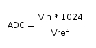
Vin is the analog input source. Vref is the reference voltage. This can be either AREF, AVcc, or a fixed 1.1V voltage. This is also selected in the ADMUX register.
A conversion can be started in different ways. You can use the ADSC bit in ADCSRA to start a conversion. If you have set ADATE to 1, it will continue to calculate the value for ADC. If you have left the value to 0, only one conversion will be done.
On the emulator the following dialog can be used to work with the analog to digital converter:
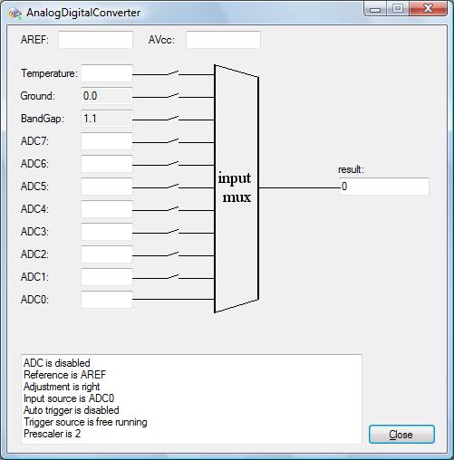
You see the multiplexer in the middle. Depending on the ADMUX register one of the input sources will be selected. You can fill out the voltage reference you use at AREF, or AVcc. You can fill out the voltage source at the line that is selected. Then the emulator will be ready to do the conversion.
To see the actual conversion go to the register screen. Make sure the emulation is running. Find the register called ADCSRA and set the bit ADSC to 1.
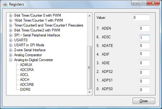
After a short interval the value of ADSC will return to 0 and the result will be available in the ADCH, and ADCL registers. In the screen the result will be available in the right side text box. Normally the value is between 0 and 16383. It is up to your software to see what the value actually means. (eg. the level of the water in a bath tub).
 |
 |
 |
|
© COPYRIGHT 2010 Imre Leber |