
 |
|
|
Home | Screen shots | Documentation | Download | Contact | Blog |
External interrupts
The AVR has a number of external interrupt sources. These triggers interrupts on the processor that make the processor jump to a different address called an interrupt service routine.
There are two different ways in which the AVR external interrupts can be programmed:
the INT method
the PCINT method
the INT method
There are 2 pins, called INT0 and INT. These are the more flexible interrupt sources. An interrupt can be triggered by the following ways:
a low level
a rising edge
a falling edge
Further more the selection of the interrupt trigger can be programmed using the interrupt sense control bits in the EICRA register.
You can mask which interrupt will trigger using the bits in the EIMSK register. Writing a one in either the INT0, or INT1 bit will allow the interrupt to occur. On condition that the I bit is also set in the status register.
When an interrupt source has been triggered, the INTF0 and INTF1 bits in the EIFR register will be set. If the INTF0 and INTF1 bits are set the CPU will initiate an interrupt if the I bit is the status register is set.
the PCINT method
There are 23 interrupt sources that can be used with the PCINT method. Either a falling edge or a rising edge can trigger an interrupt and there is no way to select which change will trigger an interrupt. Notice that PCINT15 does not exist on the arduino.
Each of the 23 interrupt sources can be masked by a bit in one of the PCMSK0, PCMSK1 or PCMSK2 bits.
When an interrupt source is triggered, one of the bits PCIF0, PCIF1 or PCIF2 will be set. If one of these bits are set and the I bit in the status register is set. An interrupt will be triggered and the corresponding interrrupt service routine will execute.
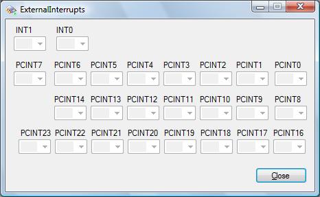
On the emulare emulator you have the following screen to change the level of the INT0, INT1, PCINT0, ..., PCINT23 pins.

Notice that initially no interrupt sources are selectable. This is because we haven't enabled them yet in the mask register.
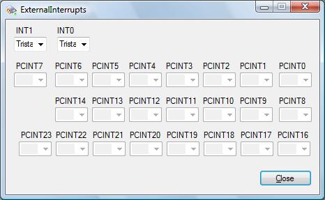
Go to registers and change the value of the EIMSK register to 3:

See how the interrupt sources become enabled:

Now you can use the combo boxes to generate an interrupt. Depending on the values of the interrupt sense control bits (ISC00, ISC01, ISC10 and ISC11) in the EICRA register, an interrupt will trigger if you change the combo boxes from low to high, from high to low, or on a low level.
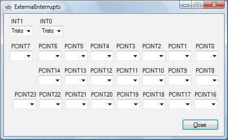
Working with the PCINT sources is very similar. Go the register PCMSK0, PCMSK1 and PCMSK2 registers and enable all the interrupt sources by writing all 1's.

The combo boxes for the interrupt sources will become selectable:

Changing the interrupt sources from a low to a high, or a high to a low level will trigger an interrupt.
 |
 |
 |
|
© COPYRIGHT 2010 Imre Leber |